|
| Richards RJ Special #47-260216- build log - p2 |
|
 |
 |
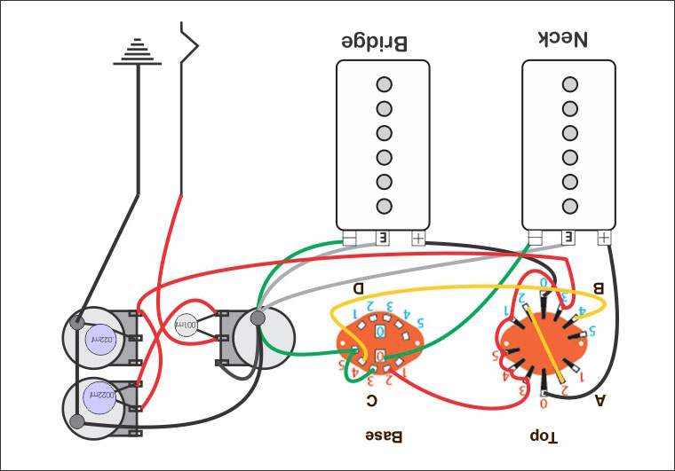
Now for some work on developing the wiring. The tone control will be replaced in the top diagram with a double gang bass / treble cut pot which will replace the tone pot. The initial issue is translating the 5 way blade superswitch into a rotary 4 pole 5 position selector called for in the design. Credit goes to Phosternix for his excellent drawing. There are many easy to follow drawings on his web site of just about any mod you can think of for the main types of pickup configs. The rotary switch pinout is shown below the wring diagram. The banks are numbered and the common terminals are marked C on the superswitch and zero on the rotary diagram. Each bank has a letter assigned to it. It is a matter of nutting out which bank on the rotary corresponds to which bank on the superswitch. |
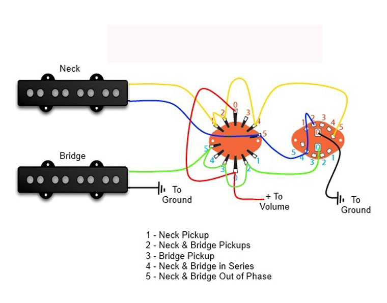 |
One way of doing it. This is an existing P Bass circuit by Eric Jaeger. The switching order is not as intuitive as the Phosternix SSOop but at a pinch this may be used if my attempt to preserve the Phosternix order below fails to deliver.
|
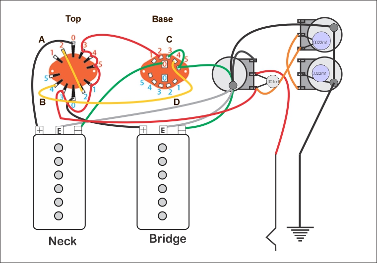 |
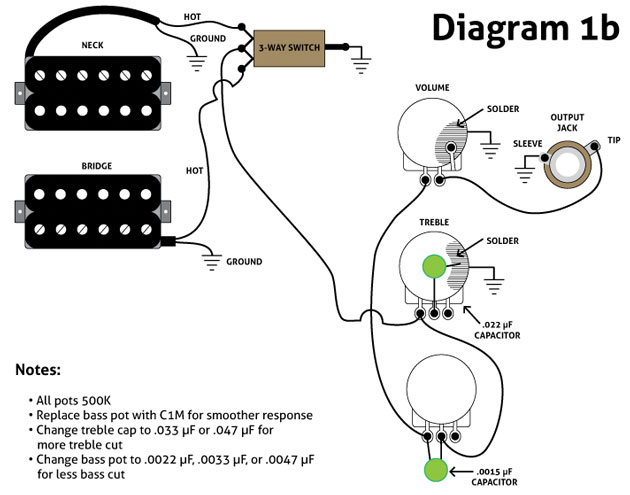
I'll try the above circuit first as it should preserve the switching order as in the Phostenix SSOop drawing above. The circuit worked but alas the PTB tone control didn't. A little digging pulled up a couple of approaches. The first looks good and easy to follow so I'll rewire the PTB the same as Diagram 1b. The second drawing :Legacy Special" lools like it was done by Robert Crumb :) It's for a strat and could be useful for a dark toned example ie one with a set of over wound stacked buckers. |
|
 |
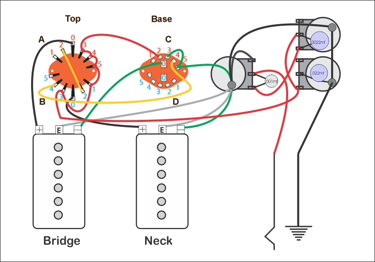
In the interests of completing the information the correct wiring diagram is posted below. Switching based on the Phosternix SSOop and the first of the two PTB circuits. |
 |
 |
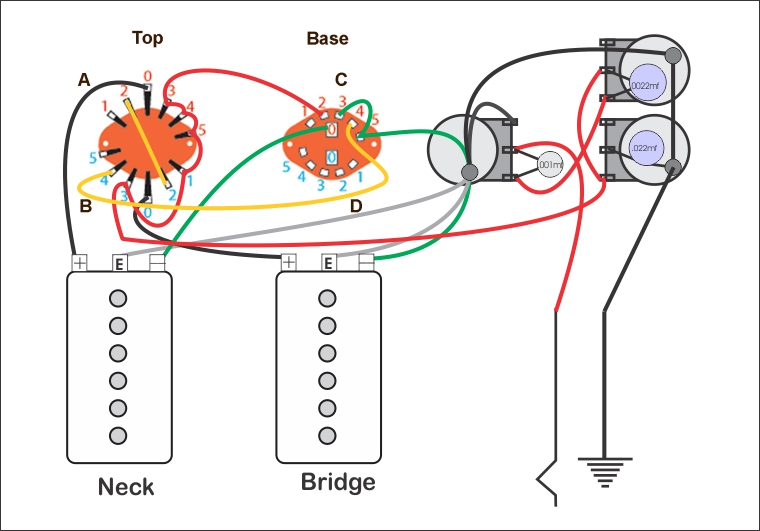
| Turns out that the pickups in this diagram should be reversed as per below |
 |
| Meanwhile back in the workshop work continues on the guitar itself, |
 |
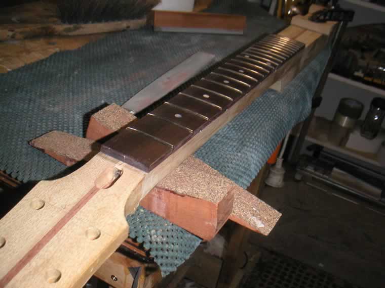
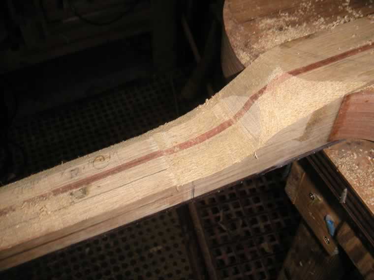
| The top bout is tried where the bottom bout will eventually be. The idea being that I want to plot the intersection of the top bout with the neck so the the transition point is accurately plotted. It is marked bottom up if you like as that is where I get most advantage for the next step which is roughing out the cross section of the neck shape on the bandsaw. |
 |
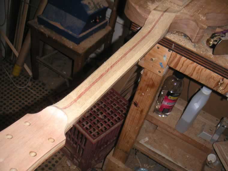
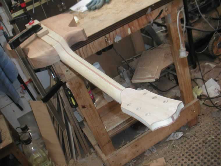
| There it is after 10 minutes and a scary momentary realisation that the knuckles on my left hand where perilously close to the blade. [NOTE TO SELF]. It looks massive but after a bit more work it will come down to size. I'd rather just cut off a little more waste than glue bits on to make up the width of the headstock. |
 |
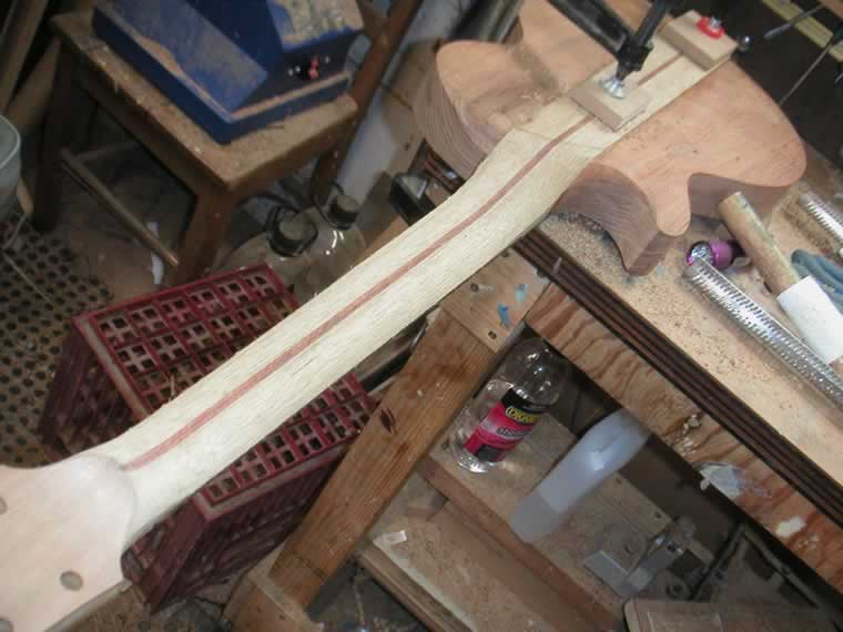
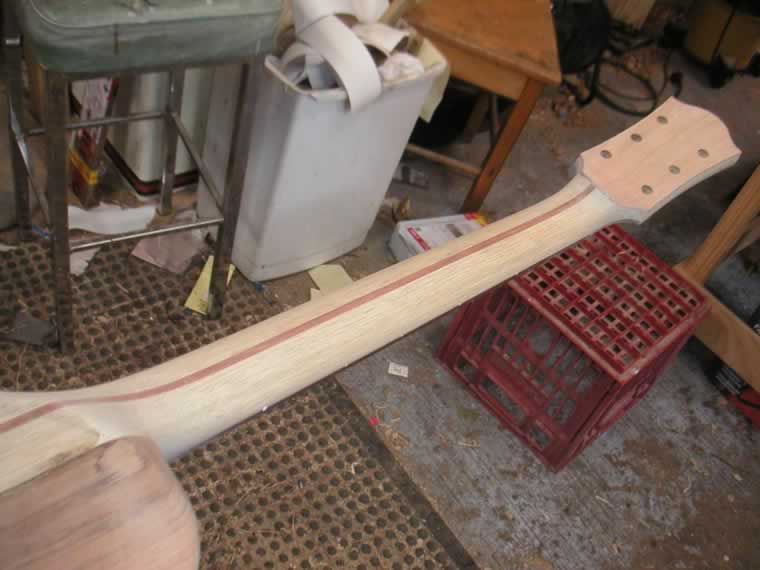
| Mark out the plan and make the final bandsaw cuts. |
 |
 |
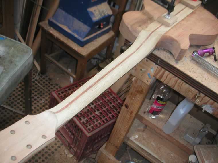
| Looking a little more in scale. Now it is just a matter of trimming the variouy planes with a router to final dimensions and it'll be time for the neck carve. Nice not to have to go through the process of measurning neck angles and mortise / neck sockets. The Limba is wonderful wood and it is quite light. It would want to be for the price I paid to get it here from America but no regrets whatsoever |
 |
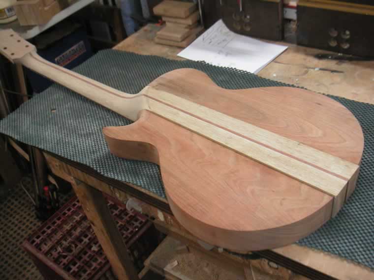
| Body machined up on all sides except the back of the neck. A small section will be taken off the top behind the fretboard after it is glued down. This will give the average hieght of Fender fingerboard crowns above the body at the back of the neck pocket. I say average as there is no definitive measure in actuality. There is a given dimension in Fender blueprints for depth of neck pocket and thickness of neck at the butt. Every one I have ever measured deviates from these measurements and I have a chart which calculates the average. |
 |
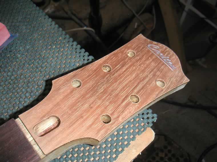
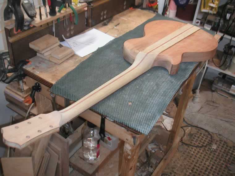
| Template is fixed to the headstock ready for machining and cutting the tuner holes. |
 |
 |
Finally we get a visual idea as to what the guitar will look like. The headstock looks a little skinny and this is intentional. The light, porous Korinna will not in my estimation suffice and will need strengthening here as this is the most vulnerable part of the design. Look at the amount of Gibson guitars with repairs where the headstock has snapped off the neck. This indicates why I beleive a single piece of Korinna here is woefully inadequate. One question is in my mind at this point regarding the blackwood control plate. It will be a thin section, so dictated by the length thread aavailable on the shanks of the dual gang pot and the 5 way rotary switch. They were designed with plastic or metal in mind. Maximum thickness will be around 3mm. The attachment screws at each end of the plate will be very close to the end of the plate [endgrain]. A bad design mechanically as a little too much pressure on the screws will cause the 2-3mm edge of the brittle blackwood to split. I mneed to make some kind of laminate and my initial thought was epoxying the blackwood to a piece of .75mm copper sheet to strenthen things up. This is a good idea in theory but in practice may cause insurmountable problems cutting the shape. Another idea is to use carbon fiber which is cheap and very strong. |
The sequence to completion will go thus: |
| This week was spent finalising all aspects of the drawing, The vectors have produced to enable cutting of the control panel, truss rod access port cover, Headstock front plate, control plate and cutting templates for the various cavities. Also the laminated material to be used for the varioUs plates were rough sawn, machined to thickness and glued as necesary. |
 |
| blackwood headplate stock |
 |
| Korina prepped for the trussrod cover. The sheen of the polished wood can easily be seen. There is no finish here this is just the shine off the timber. |
 |
| Jarrah veneer glued to the korina truss rod cver plate for strength |
| Control plate is a laminate of korina and 2mm plastic sheet |
 |
| the top headstock plate. |
 |
| Calculating the bridge position |
 |
Measuring up to ensure holes can be cut on existing equipment. A new body shape is never guaranteed to fit the machines in the workshop. Should be ok but with a couple of mm still in doubt until it phyically goes into the hole :( |
 |
| Proposed carve at the heel transition. Radical departure from the LP style transition but with a neck through design I dont have to worry about a mortise for the neck. It will look and feel sleek plus allow excellent access to the upper treble side frets. |
 |
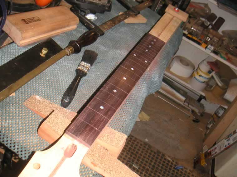
| cutting the nut angle on the headplate - last job before fretboard goes on. I'll glue that on any time after the fingerboard is glued down. |
| As I proceed I tend to think things through on virtual paper. As each build is different the process morphs to match the requirements of the build. At this point I have the end game in sight and my process notes follow. |
Instead of posting pics of every one of the myriad small tasks from this point I've posted a task list below and marked tasks XXXX as they are completed. I'll post pics of the major transition points only. |
| Updated fingerboard glueing sequence |
| Three cauls are required one wide enough to clamp betweeen 1st fret and nut exposing the fret
slot. Another wide enough to clamp the last 3 frets exposinging the fourth. The main caul
will fill the gap between the two small cauls exposing the target fret slot 1 and 4th from
high end of fingerboard. You will use 3 x 25mm brads as locating pins wich will be either
driven into neck and left or withdrawn at glue up. A good round toothpick will be required.
method Ensure both glue area are freshly sanded and level If it's Rosewood board wipe over glue area with acetone or shellite Sand nut edge angle into headstock front plate [nb plate not glued on yet] Line up centre lines & clamp fingerboard securely with long caul in center Mark FB extremities both ends with pencil Remove FB and mark the taper which can be bandsawn now if you like Locate & drill pin holes in 3 locations 1st & 9th fret slot & 3rd or 4th from end of FB Use a 1" brad or 5/64" bit & drill a test hole - ensure brad is a good fit test fit pins in fingerboard remove pins and clamp finger board to neck with long caul ensuring centers are right Tap pins into holes either end and ensure they are at least 5-6mm into neck Clamp both ends with sort cauls Remove long caul Tap in center pin [9th] ensure it is in to depth remove center pin and prepare a toothpick as a plug [must be just below FB surface] withdraw toothick plug and replace pin Remove one end caul and tap in pin Remove caul from other end and tap in pin remove finger board with pins still in ensure all pins are into neck far enough do a test test fit ensure holes locate ok and everything lines up center remove and apply glue to both surfaces Fit fingerboard on, locate and tap all pins home clamp either end with short cauls leave pins in place Either cut off pin and drive below surface or Remove center pin and fit toothpick into hole long caul clamped down with 3 clamps At this stage you can remove cauls either end, remove pins and reclamp Or leave pins in place to be removed after glue has gone off**** Add more clamps to long caul clean up squeeze out Recheck for center - easier to pull it off now than after the glue goes off Final clean up ****Removing pins may allow closer unimpeded clamping |
 |
 |
 |
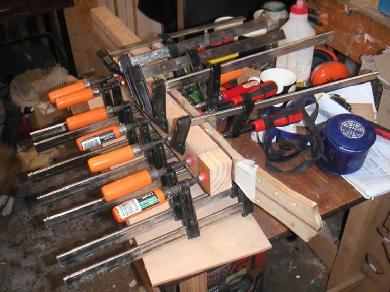
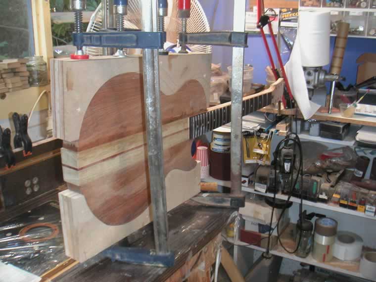
| Things go quiet now for 3 days while the headplate, top and bottom wing are glued on. One glue down per day aas I can't do much to the job while the clamps are on. As soon as the last clamp is off I am on the whipping side as the neck carve and body cavities can be completed during the end game of the build. |
 |
 |
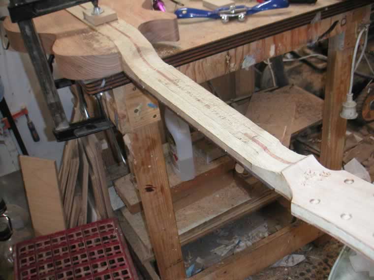
| Last bits glued on - so from here it's just a matter of removing the bits that don't belong. This time I start with carving away the shavings and sanding dust concealing the neck buried deep inside the wood |
 |
 |
 |
 |
 |
 |
 |
 |
 |
|
 |
| Now for the cavities - the final job in the build |
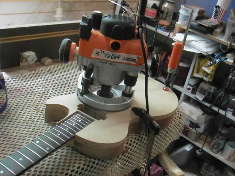 |
| Template in place and after a while: |
 |
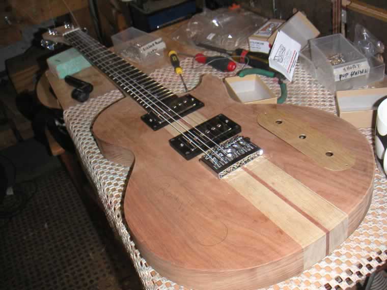
| Now for the bridge placement and a test string up. For future reference half scale is 311.5 mm and witness point at bridge for a .035" action at the 12th fret was 313mm on the treble E string. |
 |
 |
| So that's pretty much the end of the build. Next shot will be the finished guitar. In the meanrtime sanding and a burnished oil finish will be applied. While the finish cures the wiring will be tackled. |